Telehandler Rated Capacity Limiter 'RCL'

Know your Limits, set your Height & Reach Limits

The Telehandler Rated Capacity Limiter 'RCL' with integrated Height & Reach limiter is a culmination of the current research and development efforts conducted by the OEM.  The Tele-RCL takes advantage of the most recent developments in embedded processing and display technology to provide the most advanced and intuitive system in the market place.  Keeping the operator within the Rated Capacity Limits in real time well enabling the ability to set Height & Reach Limits to suit the site conditions.


Features

  • Sunlight readable High Definition Graphic Display
  • The ability to set Height & Reach Limits
  • LMI and RCL dual system processing with one single operator display
  • Advanced operator information including rating chart display and dynamic stability triangle
  • Automatic or manual tool selection with operator verification
  • Machine reverse camera and forward blind side camera (Option)
  • Wireless dogman (helmet) / job site camera optional for remote load positioning (Optional)
  • Modern slim line display with high fidelity audio output
  • System status notifications via audio tones or voice messaging
  • User input via automotive dash mounted dial control
  • Automatic fault detection and diagnostic screen
  • Operator identification login as standard via identification card
  • Customisable graphic display skins
  • Data logging functionality of all events and black box data storage redundancy
  • Fast installation time
  • Quick configuration for machine type and language
  • System holds all data for all machines, eliminating the requirements for firmware updates
  • Automatic system calibration via software tools
  • Modular design that can be upgraded with the addition of plug and play modules
  • Modular system architecture with CAN bus interconnection


Cameras

Camera features

The Tele-RCL has support for multiple cameras.

A reverse camera, a front blind side camera and a portable remote camera.


When a camera is engaged the display layout changes to camera mode.  The rating chart and stability triangle are replaced by the camera window.  This allows the operator to both view the camera and still have a view of the current load and capacity from the status window.  However when an overload event occurs this is prioritised and the display will switch back to normal mode to allow the operator to view and analyse the rating chart and stability windows.


The majority of service issues relate to damage to the front right tyre, due to the fact that the boom obscures the operator’s view when performing pick and carry operations.  To solve this problem a camera is installed to display the view from the front right tyre.  When the operator places the machine in forward gear the camera is activated to show any obstructions that the operator may run into.


A third remote camera can be placed anywhere around the machine.  It can be placed on the front of the boom to allow the operator to see what they are lifting or it can be placed on the dogman’s helmet to allow the operator a view from the dogman’s perspective or any other place it is needed.

Screen Layout

Load Percentage

The load percentage display shows the current load as a percentage of the maximum load according to the rating chart for the current boom position.  It displays both a percentage bar and the value.

The percentage bar is colour coded depending on the percentage.


The bar is green when the capacity is between 0 – 79 percent.

The bar is yellow when the capacity is between 80 – 99 percent.

The bar is red when the capacity is greater than 100 percent.

The Tele-RCL can be integrated with the machine’s existing Load Moment Indicator (LMI) or the LMI percentage can be calculated from the current load.  When displaying LMI the load percentage changes to two bars.  The RCL percentage is displayed on the top bar with the LMI percentage displayed on the lower bar.  The percentage value displays the highest of the two values.

Attachment

This displays the description of the currently selected attachment to allow the operator to clearly see which attachment configuration the Tele-RCL is using.

Rating Chart

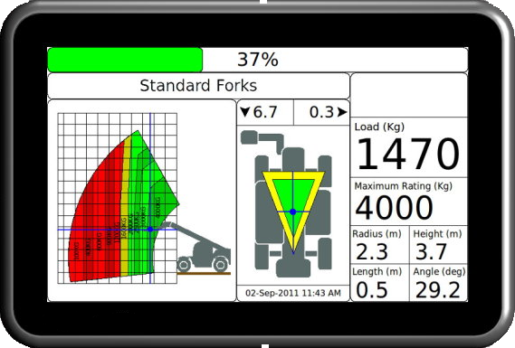
The Tele-RCL displays a fully dynamic rating chart for the selected attachment.  With the telehandler overlay it allows the operator to quickly determine at a glance the current location within the boom’s range of movement and how much further the boom can be extended with the current load.  The rating chart also incorporates a zoom feature which allows the operator to zoom into the rating chart for further detail.


The load segments on the rating chart are colour coded to match the current load.  If the segment is green and the boom is moved inside the segment the rated capacity percentage would be between 0% – 79%.  If the segment is yellow the capacity would be between 80% – 99% in that region and if red the capacity would be 100%+ in that region.  This allows the operator to lift the load and determine the boom range before the lift is performed.


The rating chart also has an image of the telehandler showing the current boom location within the chart.  The telehander image also changes the attachment to match the currently selected attachment.  When both stabilisers are lowered the telehandler image is updated with stabilisers shown in front of the tyre.


The current position within the chart is shown via crosshairs.  With the chart grid in 1 metre increments the operator can determine the distance the load can be safely moved.


For more detail the operator can zoom into the chart.  This will zoom into the current load centre location in the chart, as the boom approaches the edge of the chart the window will slide along to keep the load centre in view.

Stability

The stability triangle shows the current centre of mass of the telehandler taking into account the lifted load and the carrier angle.  The centre of mass location is indicated by the crosshair.  The centre of mass is overlay over the stability triangle, which is drawn between the front tyres and the centre of the rear axle.  If the centre of mass moves outside of the triangle there is a danger of tipping the telehandler.  When both stabilisers are lowered the stability triangle is redrawn between the stabilisers and rear axle.


The longitudinal carrier stability angle is shown in the top left corner of the stability window.  The lateral carrier stability angle is shown in the top right corner of the stability window.  Arrows are shown beside the each carrier angles to indicates the direction of the carrier tilt.


When a stabiliser is lowered the telehandler image is updated to show the new stabilser down state. When both stabilisers are lowered the stability triangle is enlarged and redrawn between the stabilisers and rear axle. If one of the stabilisers is not down and pressurised the stability triangle remains between the front tyres and rear axle.

Status

The status window shows all the numerical values related to the load and the boom location.


The top of the status window is the status icon area, when any events that the operator needs to be aware of such as an overload the cutout icon will be shown in the icon area.


Below the status icons is the current load and the maximum capacity as defined by the rating chart, both are displayed in large easily readable text.


At the bottom of the status window are the boom position values; radius, height, boom length and boom angle.

System Components

Integrating Sensors & Modules with a rugged CAN-Bus network

In-Cab Display

The In-cab Display Module is a state of the the art embedded computer specifically designed for use with industrial lifting equipment.  The slim line display features a 7” wide screen high definition LCD screen capable of displaying high quality graphics to better assist the machine operator.  The display unit incorporates stereo speakers with advanced warning alarms via tones and voice messaging.  The In-cab display takes advantage of the latest in technology providing the operator with information such as the digital rating chart with forward prediction, active shading and zoom, plus the machine dynamic stability triangle.  The In-Cab Display has a NTSC / PAL video input used for reverse, forward and remote cameras.  The  In-Cab safety processing software and operating system is easily updated via an on-board SD card, the display operating system includes advanced menu functions for instant system configuration and diagnostics.

Interface Module

The Cabin Interface Module is a universal and fully configurable digital I/O module, with smart power management and backup battery.  This unit has a small footprint and is designed to be mounted within the cabin of a machine to provide the interface between the machine electrics and the Tele-RCL technology.  The Interface Module has an array of configurable input and output channels that can be used to sense signals such as outrigger positions and control machine motion cuts.  The module features tri state input channels to effectively handle any type of digital input signal thus eliminating the need for signal conditioning on the machine side.  This module incorporates smart power management circuitry along side the back up battery which is used to keep a portion of the system powered for the GPS tracking and 3G data access in the event that the main power source is lost.  The module additionally incorporates a universal analogue input and a dedicated machine override timer, all connections into the module are made via a robust easy to use, aviation grade snap lock connector system.

External Light Tower Module

The External Light Tower Module is designed to provide personnel outside the machine, an indication of the current machine state.  The ELTM receives information from the safety system which relates to the machines state of operation.  The module comes standard with three indication states of green, yellow and red, additional indication states can be added if required.  The light tower uses LED’s to illuminate each colour section, these LED’s operate at low power and have an increased life over traditional indication solutions, making the module robust and long lasting.

Pressure Input Module

The Pressure Input Module functions as an integrated system node for pressure / load measurement, level calculation and external I/O control.  The PIM contains a dual axes inclinometer used for machine chassis level determination and several digital inputs and output channels that can be configured for outside cabin use as required.  The PIM has been designed to accommodate a wide variety of sensor inputs for the purpose of load, tension and pressure measurement.  The sensor input channels can connect to any style of pressure or load sensor device for easy adaptation and migration from application to application.  The PIM is housed in powder coated die-cast aluminium IP69 rated enclosure giving the unit unparalleled protection in harsh environments. The PIM connects to the main system processing node via a CAN bus allowing the unit to be positioned without the need for complex wiring configurations.

Angle & Length Module

The Angle and Length Module is designed as a small all-in-one unit for measuring angle and length in industrial lifting applications.  The unit has been designed to fit onto the outside or inside of a telescopic boom, with its small footprint, low profile and M12 screw lock connector system makes it easy to install. The Angle and Length Module uses unique quadrature encoding for the length measurement and solid state accelerometers for angle determination, making the unit fully digital and self calibrating.  The internal recoil spring is protected against reverse recoil in the event of trace cable breakage via an internal clutch mechanism.